Count inputs and rack space separately
Keysight introduced the XR3 low-profile oscilloscope on November 3, 2026. It fits in one rack unit (1U) and has four analog channels. A hypothetical team that needs 12 analog inputs could fit three XR3 units into 3U before allowing for signal distribution, cabling and other equipment. That counts physical inputs; it does not establish that the channels are aligned in time.
That distinction matters. More channels can reduce the need to re-patch signals, but channel count alone does not guarantee time alignment, low skew, or consistent measurement quality across instruments. If the goal is to observe one event on many signals at once, the first question is not how many inputs the rack can hold. It is whether those inputs can be compared with enough confidence for the test being performed.
What the 14-bit spec does and does not tell you
Keysight describes the XR3 as a 14-bit oscilloscope, which is a nominal converter resolution. That is not the same as effective number of bits, and it is not a promise of overall accuracy in every operating mode. Real-world results depend on bandwidth, front-end settings, probe choice, signal amplitude, and the noise floor of the actual test environment. A 14-bit ADC can be helpful, but it should not be treated as a guarantee of cleaner traces by itself.
For a team deciding whether to add more XR3 units, a sensible validation step is to feed a common known signal into multiple instruments using comparable cables, probe paths, and front-end settings. Then compare trigger alignment and timing variation between scopes. If the same waveform is acquired on different units, any offsets or jitter-like differences should be measured under the same bandwidth limit and configuration that the team plans to use in production testing.
A practical rack test before scaling up
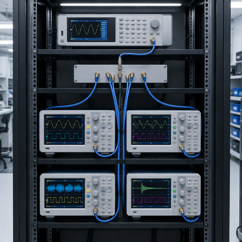
A useful pre-deployment check is simple: choose a stable reference signal, distribute it to each instrument, and record repeated captures while keeping the setup as identical as possible. Watch for trigger placement differences, channel-to-channel skew, and any variation that changes with scope settings. Then repeat the test in the actual bandwidth the application requires, because a configuration that looks clean at one setting may behave differently when the front end is opened up.
This approach is especially important in a mixed rack where the scopes are only one part of the system. Three XR3 units may give a team 12 physical inputs, but the value of those inputs depends on how well the instruments agree with each other and how much uncertainty the test can tolerate. If the application needs precise correlation across many channels, it is better to verify synchronization behavior directly than to assume it from the channel count.